

Under the framework of:

Sponsors:


The validation of the Equimetrix system presupposes the simultaneous collection of data with standard systems (gold standard) in order to evaluate the accuracy and precision of the data obtained by this system. In the design stage it was determined that optical and inertial systems should be used for the validation of the estimation of the center of mass (CoM) position, as well as baropodometric and dynamometric solutions for the comparison of the pressure center (CoP) position and the support base (BoS).
The general objectives of the project foresee four main points:
To date, efforts have been made to complete the first three objectives of the project, although there are some deviations from expectations due to the need to adapt the project to reality. During the project, and when testing the equipment in competition with the Equimetrix system, it was found that the inertial kinematics system for CoM measurement and the podobarometric system for CoP measurement are not fully compatible with the operation mode of the Equimetrix system, making its comparative use impossible. These deviations from the project are described and justified in detail in section 3 of this report.
The non-use of the inertial kinematics system for the measurement of the CoM and the podobarometric system for the measurement of the CoP due to technical impossibilities compromises the achievement of some of the objectives foreseen in the project but, ultimately, we believe that it is beneficial to the project, providing a simplification of the equipment and procedures that, given the redundancy of the equipment for the validation of the CoM and the CoP, allow the achievement of the main objectives.
Thus, the project is working with the use of the optical kinematic system (Qualisys, Sweden) for CoM validation, the force platform (dynamometry) for CoP validation and the baropodometry for BoS validation. From the outside, the inertial system (Xsens) is used for CoM validation and baropodometry for CoP validation. Given the compatibility of the equipment in use, the conditions were met that made it possible, through a single session, to gather data that allowed Objectives 1, 2 and 3 to be achieved. Objective 4 "Validation of the training functionalities provided by the Equimetrix system", for which objective 1.6 "to create a protocol for evaluating the balance and postural regulation training functionalities with subjects with different characteristics" is currently under preliminary testing.
Considering the situations described above, it can be stated that Objective 1 "Definition of ethical evaluation and certification protocols" is 75% complete, and that the remaining 25% is related to Objective 1.6. Likewise, Objective 2 "Validation of baseline measurement, pressure centre migration and stabilization" and Objective 3 "Validation of the estimation of the three-dimensional centre of mass position" are complete with regard to their data collection.
The collected data are being processed and a dedicated analysis routine has been created at Matlab (Mathworks Inc., USA). It is estimated that by the end of October the analysis of these data will be completed and the data collection necessary for the achievement of Goal 4 will begin.
2. Details of results achieved in relation to each of the proposed objectives and targets
This section describes the progress made in achieving each of the objectives set out in the project. Due to simultaneous data collection, it is not possible to divide the protocol below into sub-sections for each Objective. In order to facilitate reading and analysis of the efforts made, this section is divided into several subsections, each relating to a phase of the validation process.
2.1 Definition of ethical evaluation and certification
The first objective of the project consists of six points that lead to the establishment of appropriate protocols for the validation of the Equimetrix system. Since the CoM measurement system (Qualisys, Sweden) and the CoP measurement system (Bertec Platform, USA) are integrated into one system, it was possible to design a simultaneous validation protocol. The validation of the BWS, although it cannot be carried out simultaneously, could be done later. Thus, the protocol obtained (Protocol A) is characterized by condensing in a single one-hour session all the evaluations needed to validate the CoM, CoP and SoB, without the need to change the experimental setup to perform each task, or to subject the volunteer to several different and/or repetitive test conditions.
Table I - Equipment in use in the validation protocol, its nature and purpose of validation
%20-%20catia%40wildwildweb_es%20-%20Correo%20de%20Wild%20Wild%20Web%20Studio_%20-%20mail_google_com.png)
Protocol A aims to achieve objectives 1.1, 1.3 and 1.4. Objectives 1.2 and 1.5 cannot be achieved due to the technical issues described in section 3 of this report. Protocol 1.6, as far as the validation of the training functions of the Equimetrix system is concerned and as such associated with Objective 4, will be the subject of a separate validation protocol (Protocol B) which has not yet been finalised.%20-%20catia%40wildwildweb_es%20-%20Correo%20de%20Wild%20Wild%20Web%20Studio_%20-%20mail_google_com.png)
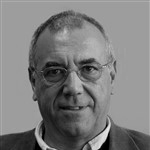
Figure 1 - Illustration of the calibrated volume (semi-transparent pink) and the relative position of the volunteer inside seen in the (a) sagittal plane, (b) frontal and (c) transversal.
To model the body of the volunteer, retroreflective markers were placed in several anatomical points to allow the subsequent 3D reconstruction in the Visual3D biomechanical analysis software (C-Motion, USA), and the calculation of its CoM. The whole body model used can be seen in figure 2. A more detailed image can be found in section 7 of this report, as well as a table explaining the nomenclature used to identify the selected anatomical points. Note that although no markers have been placed on the head segment, it was also modeled as belonging to the trunk segment.
%20-%20catia%40wildwildweb_es%20-%20Correo%20de%20Wild%20Wild%20Web%20Studio_%20-%20mail_google_com.png)
Figure 2 - Whole body biomechanical model implemented for the calculation of the center of mass.
Before starting the data collection procedure, a collection was performed with the volunteer in an anatomical position to obtain a record of the position of all the markers. All kinematic collections were made with an acquisition frequency of 200 Hz.
The volunteer was placed on a Bertec force platform (Bertec inc. USA) with a size of 90x60cm and operating at an acquisition frequency of 2000Hz, with the data of the reaction forces on the ground, the moments of force and the position of the centre of pressure being collected simultaneously and in sync with the kinematic system.
The Equimetrix system was placed on the force platform in such a way that the center of its sensor mat was aligned with the center of the force platform. The sensory pattern on which the Equimetrix system bases its global three-dimensional reference frame was identified using the retroreflective tape to reproduce the origin and axes of this reference frame.
%20-%20catia%40wildwildweb_es%20-%20Correo%20de%20Wild%20Wild%20Web%20Studio_%20-%20mail_google_com.png)
Figure 3 - Representation of the placement of the retroreflective tape in (a) the optical pattern and (b) the camera and harness of the Equimetrix system.
The camera used by the Equimetrix system to identify the optical pattern and thus estimate the position of the CoM was placed on the volunteer's trunk according to the manufacturer's recommendations. In order to identify the relative position of the camera on the volunteer's trunk, as well as its inclination and distance from the general reference of the Equimetrix system, retroreflective tape was placed on the camera and its support harness.
These three equipments (kinematic system, force platform, Equimetrix system) were used together to validate the CoM and the CoP, an example of this experimental configuration is illustrated in figure 4.
%20-%20catia%40wildwildweb_es%20-%20Correo%20de%20Wild%20Wild%20Web%20Studio_%20-%20mail_google_com.png)
Figure 4 - Example of the experimental set-up for the validation of the CoM and CoP integrating the optical kinematics system, the dynamometry (force platform) and the Equimetrix system.
Although the kinematics and the dynamometry system are synchronized with each other, the Equimetrix system does not have any electronic synchronization mechanism. Therefore, a mechanical synchronization method has been implemented, which consists of simultaneously supporting the sensory mat of the Equimetrix and the force platform. Since the Equimetrix is on the platform, this support will be recorded simultaneously and expressed in a substantial and momentary increase in the value of the vertical force (on the force platform) and the support base (on the Equimetrix system).
A Walkway Baropodometer mat (Tekscan, USA) operating at an acquisition frequency of 100 Hz was used to validate the support base.
2 2.2 Sample Recruitment
To carry out the validation collections, a sample composed of 20 volunteers (males: 8; females: 12) of 32.6 ± 8.9 years of age and 168.5 ± 10.1 cm in height, 70.6 ± 12.6 kg of mass, body mass index of 24.8 ± 2.9 and the performance of sports 3.3 ± 1.7 days a week was collected. All volunteers have the right to dominate the members. The characteristics of the sample are shown in detail in Table II.
%20-%20catia%40wildwildweb_es%20-%20Correo%20de%20Wild%20Wild%20Web%20Studio_%20-%20mail_google_com.png)
Table II - Characterization of the sample recruited in terms of sex, age, height, mass, indicates the body mass (BMI) and the weekly physical activity, expressed as mean ± standard deviation and value (min. - max.)
The sample consists of healthy volunteers with no recent musculoskeletal injuries, no known motor or neurological pathologies, no serious visual or hearing disorders and preferably engaged in physical activity.
7.2.3 Data collection procedure
The data collection session began with a survey to determine whether the page voluntarily meets all the criteria for inclusion in the sample. The volunteer was then asked to remove his or her shoes and socks, and the outline of the foot was drawn on an A3 sheet of paper in the positions described in Table III, which are the tasks to be performed by the volunteer.
Table III - Description of the positions and stabilometric assessment tasks implemented and their sequence of execution
%20-%20catia%40wildwildweb_es%20-%20Correo%20de%20Wild%20Wild%20Web%20Studio_%20-%20mail_google_com.png)
Then, the retro-reflective markers were placed on the volunteer according to the biomechanical model of the body, as well as the camera of the Equimetrix system.
The collection procedure started by placing the A3 sheet with the position to be tested on the sensory mat of the Equimetrix, which was on the force platform and within the volume calibrated for the kinematic system. The order of execution of the tasks could not be random, since some of them require the elimination of the retroreflective markers. Since it is not possible to guarantee their exact replacement, which could generate undesirable and unforeseen changes in the reconstruction of the segments and in the estimation of the CoM, it was decided to follow an order of tasks that would allow the selective removal of the markers.
The volunteer placed his feet on the sheet to ensure that the feet met the previously designed limits. Data collection was initiated simultaneously in kinematics, dynamometry and the Equimetrix system.
Two synchronization events occurred, one immediately after the start of the collection and the second after the end of the collection period planned for the task.
During the collection period the volunteer was instructed to remain in a stationary position, without the possibility of moving his legs, arms or head, and to fix a point 5 meters away and at eye level. In the case of squatting tasks, the volunteer was instructed to try to keep the trunk vertical, being able to use the upper extremities to maintain balance, and to perform the five squats at a speed selected by himself. The entire squatting posture began and ended in a bipodal position.
Once the data collection was completed on the platform and the Equimetrix force system along with the kinematic system, the plates with the contours of the feet were placed in the podobarometric system. The volunteer was again instructed to place his feet on the sheet to meet the contours, and to remain in a stationary position, and a 10s collection was performed to record the contact area provided by the task. The placement of the leaves on the ground and the completion of the different tasks was random, since this task did not depend on the existence of markers.
2.2.4 Data processing procedures
The data collected by the kinematics system was processed in the Qualisys Track Manager software (Qualisys, Sweden) to identify the markers, eliminate undesirable artifacts and reflections, and interpolate any faults in the marker paths.
The kinematic and dynamometric information was then imported to the Visual3D software (C-Motion, USA) where the reconstruction of each segment of the volunteer's body was performed, thus allowing to obtain his CdM. The CoP recorded by the force platform was also calculated. Since the reference system of the model is different from the one used, both the CoM and the CoP information were calculated in relation to the reference origin of the Equimetrix system. Two analysis routines were developed in Matlab (Mathworks, USA), one for CoM and CoP analysis and one for BoS analysis.
Then, retro-reflective markers were placed on the volunteer according to the biomechanical model of the body, as well as the camera of the Equimetrix system.
The collection procedure was started by placing the A3 sheet with the position to be tested on the sensory mat of the Equimetrix, which was on the force platform and within the volume calibrated for the kinematic system. The order of execution of the tasks could not be random, since some of them require the elimination of the retroreflective markers. Since it is not possible to guarantee their exact replacement, which could generate undesirable and unforeseen changes in the reconstruction of the segments and in the estimation of the CoM, it was decided to follow an order of tasks that would allow the selective removal of the markers.
The volunteer placed his feet on the sheet to ensure that the feet met the previously designed limits. Data collection was initiated simultaneously in kinematics, dynamometry and the Equimetrix system.
Two synchronization events occurred, one immediately after the start of the harvest and the second after the end of the harvest period scheduled for the task.
During the collection period, the volunteer was instructed to remain in a stationary position, with no possibility of moving his legs, arms or head, and to fix a spot 5 meters away at eye level. In the case of squatting tasks, the volunteer was instructed to try to keep the trunk vertical, being able to use the upper extremities to maintain balance, and to perform the five squats at a speed selected by himself. The entire squatting posture began and ended in a bipodal position.
Once the data collection was completed on the platform and the Equimetrix force system along with the kinematic system, the plates with the contours of the feet were placed in the podobarometric system. The volunteer was again instructed to place his feet on the sheet to meet the contours, and to remain in a stationary position, and a 10s collection was performed to record the contact area provided by the task. The placement of the leaves on the ground and the completion of the different tasks was random, since this task did not depend on the existence of markers.
CoM and CoP analysis routine
This first routine accepts the CoM information calculated in the Visual3D software, as well as the CoP and the vertical force recorded by the force platform. It also allows importing the data file generated by the Equimetrix system.
The data from the Visual3D software (V3D_CoM and V3D_CoP) is synchronized with the CoM estimate provided by the Equimetrix system (EQM_CoM). This is done using the mechanical synchronization event described above, using the vertical force and BoS information from Equimetrix. Since the events were recorded by both systems simultaneously, the period between the two events should be the same, regardless of the sampling frequency of each system. Thus, the end of the first synchronization event and the beginning of the second event were determined and, therefore, the collection period for each acquisition system. This period was then resampled to consist of 1,000 points, the first corresponding to 0% and the last to 100% of the task execution period.
%20-%20catia%40wildwildweb_es%20-%20Correo%20de%20Wild%20Wild%20Web%20Studio_%20-%20mail_google_com.png)
Figure 5 - Identification of the beginning (vertical red line) and end (vertical green line) of the harvesting period performed by (a) the kinematic and dynamometric system and (b) the Equimetrix system.
After normalisation of the time scale all signals are subjected to smoothing using a moving average with a 20 point window.
%20-%20catia%40wildwildweb_es%20-%20Correo%20de%20Wild%20Wild%20Web%20Studio_%20-%20mail_google_com.png)
Figure 6 - Illustration of the anterior-posterior component of the data from V3D_CoM (blue), V3D_CoP (green) and EQM_CoM (red), illustrating their appearance a) initially and b) after the application of the 20 point moving average smoothing.
The CoM and CoP migration is designed in the form of a statokinesiogram to observe how they migrate in space over time. Given the dispersed nature of this migration, an ellipse covering 95% of its route is calculated and superimposed, as illustrated in Figure 7.
%20-%20catia%40wildwildweb_es%20-%20Correo%20de%20Wild%20Wild%20Web%20Studio_%20-%20mail_google_com.png)
Figure 7 - Statokinesiogram and its migration ellipse in (a) V3D_CoM space, (b) EQM_CoM and (c) V3D_CoP.
The following comparisons are made between the signals, in their antero-posterior (AP), mid-lateral (ML) and vertical (V) components
BoS Analysis Routine
The comparison of the support base of the Equimetrix and Walkway system is done through a dedicated routine.
From the data collected by the Walkway system, the AP and ML distance of the registered contact areas is determined and compared with the BoS data determined by the Equimetrix system.
3. Justification of deviations from the work program
When the preparation of the evaluation protocol and the validation procedures for each measure provided by the Equimetrix system were initiated, several preliminary and exploratory collections were made. The purpose of these was to identify possible incompatibilities of the gold standard systems with the Equimetrix system, as well as to test the validity and reproducibility of some procedures.
From these initial tests, two situations were identified that make it impossible to meet some objectives, namely validation of the CoM and CoP using inertial kinematics and the podobarometric system, respectively. These situations are described in detail in the following subsections.
3.1. Evaluation of the CoM by the Chinese inertial system
The Equimetrix system performs its CoM calculation using optical means. To do so, it has an optical pattern placed after the sensory mat, and whose position is recorded by a webcam placed on the volunteer's back. This recording allows the calculation of the approximate position of the CoM.
The validation of the center of mass foreseen in the project is based on the use of two motion capture systems, one with an optical base (Qualisys) and the other with an inertial base (Xsens). The optical systems, through the use of video cameras, are equipped with greater versatility and adaptability, simply by placing retroreflective markers on the structures that are intended to obtain an exact three-dimensional position. Inertial systems, on the other hand, require the use of inertial plants (containing accelerometers, gyroscopes and magnetometers) placed in segments to determine their movement. These inertial plants are generally larger than retroreflective markers, giving them less spatial accuracy.
The definition of orthogonal references is the basic principle of position and motion identification in kinematic systems. The Equimetrix system defines its reference in a set of coordinates depending on its optical pattern. The optical kinematic system (Qualisys) determines its reference through a calibration step, but retains the ability to generate a local reference simply by placing reflector markers in the desired coordinates. The inertial system (Xsens), in turn, defines the origin of its reference frame as the place where the static calibration of the subject is performed, the origin of the frame being located on the ground approximately at the place of the vertical projection of the CoM.
Taking into account these characteristics, a technical problem underlying the use of inertial systems is shown: the impossibility of establishing with precision an orthogonal reference common to all systems. Although it is possible to reproduce the reference system of the Equimetrix using the optical kinematics (Qualisys), placing retroreflective markers in the optical pattern of the Equimetrix, it is not possible to do the same with the inertial system.
Although it would be possible to acquire data with different references, thus assuming a spatial lag of unknown magnitude, for the study of the variations of the CoM position over time, the identification of subtle differences between the systems could be questioned, which would not favor a proper validation.
Another problem is the lack of a compatible synchronization method between the inertial system and the Equimetrix system, which could add a time lag to the already existing spatial gap between the systems.
Since the use of two kinematic systems is redundant, and the optical kinematic system (Qualisys) is the gold standard for motion capture, the exclusion of the use of the Xsens inertial system does not compromise the achievement of the main objectives of the project.
Thus, there is a deviation of the project in the impossibility of implementing the following objectives:
Objective 1.5: Definition of tests and evaluation protocols of the center of mass kinematics by the 3D inertial kinematics.
Objective 3.3: To carry out a simultaneous comparative study between the Equimetrix system and the inertial motion capture system (Xsens)
3.2 Evaluation of the COP by podobarometry
The Equimetrix system consists of a sensory mat that, by applying the load, determines the area it occupies. To protect it, the carpet has a polyurethane foam on the bottom and a vindictive film on the top, which gives the carpet a lot of flexibility and a thickness of approximately 5 mm. The carpet also has a dimension of 115 x 97 cm.
The podobarometric system of the footbridge consists of a platform with pressure sensors distributed over a sensorial area of approximately 40 x 175 cm, with a rigid and non-flexible base. By placing a load on its sensory area it is possible to record not only the pressure it exerts, but also the area of contact with the mat and its pressure centre.
It was expected that placing the Equimetrix system on the catwalk mat would cause an attenuation in the value of the pressures registered by the podobarometric system due to the existence of polyurethane foam between the subject and the mat. Although the pressure value is necessary to calculate the pressure center, it is not necessary to determine the support base.
However, preliminary tests have shown that the placement of the Equimetrix system causes a pressure diffusion effect. This manifests itself as a pressure pattern that disperses beyond the support base, due to the increased contact pressure of the polyurethane foam in the vicinity of the feet, with the catwalk carpet. This phenomenon prevents not only the correct identification of the support base boundaries, but also the pressure centre. Furthermore, the small size of the Walkway system compared to the Equimetrix system and the fact that it has a high edge on one side makes it difficult to position the Equimetrix system correctly on the Walkway carpet.
The pruning system is also a redundant system for measuring the COP, with the force platform being the gold standard system for such measurement. Therefore, its exclusion as a method of validation by the COP does not compromise the achievement of the main objectives of the project.
On the other hand, the prunobarometric system was the best solution for the estimation of BoS, so it was necessary to develop a method to ensure that the volunteer performed identical support on the Equimetrix system and the prunobarometric system. This method is described in the collection protocol, as the use of an A3 sheet with the outline of the volunteer's feet, which served as a guide for the various types of support.
Thus, a deviation from the project occurs in the impossibility of carrying out the following objectives:
Objective 1.2: Definition of tests and protocols for the evaluation of pressure centre migration and stabilization by podobarometric assessment.
Objective 2.2: To carry out a simultaneous comparative study between the Equimetrix system and the pressure measurement system for pressure centre measurement and stabilometry migration.
4. The scientific output
As of the date of this report, no scientific publications resulting from this work are yet available, but it is estimated that the results obtained may allow the publication of at least two research articles in an international journal.
These publications will of course be monitored for possible progress in the implementation of the Equimetrix system.